Wallerawang - Construction, May 2010
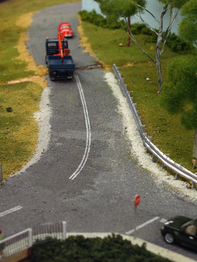
The motorists of Wallerawang can use this intersection with peace of mind now that Armco railing has been installed.
Aluminium foil was used to scratchbuild Armco railing for the T-intersection at the road bridge. A jig was made from 2 pieces of styrene rod glued in close parallel on a flat piece of styrene. A thin strip of aluminium kitchen foil was placed over the jig and then, using a piece of the same size rod, the foil was gently pressed into the gap between the 2 parallel rods. The foil then takes on the form of 2 outward curves with an inward curve between them, a reasonable representation of prototype Armco railing.
The best foil to use is the thickest available in plain form (no embossing). The pressed foil is quite fragile and needs to be handled with care to avoid destroying its shape. The upright supports for the Armco railing are short lengths of 3.2mm C-channel styrene, pre-painted metallic grey and installed in the layout scenery. The pressed foil is then glued to the pieces of C-channel.
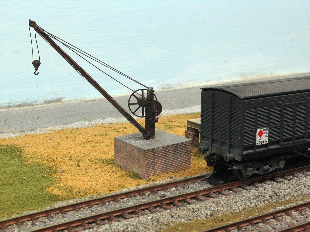
An MLV louvre van awaits pickup after being unloaded at the Goods Dock.
The Goods Shed received a yard crane to assist with the unloading of heavy objects. The crane is a Peter Boorman's Workshop kit of a standard NSWGR 5 ton yard crane. The crane was assembled and painted before being attached to a scratchbuilt platform, made from styrene and brick sheet.
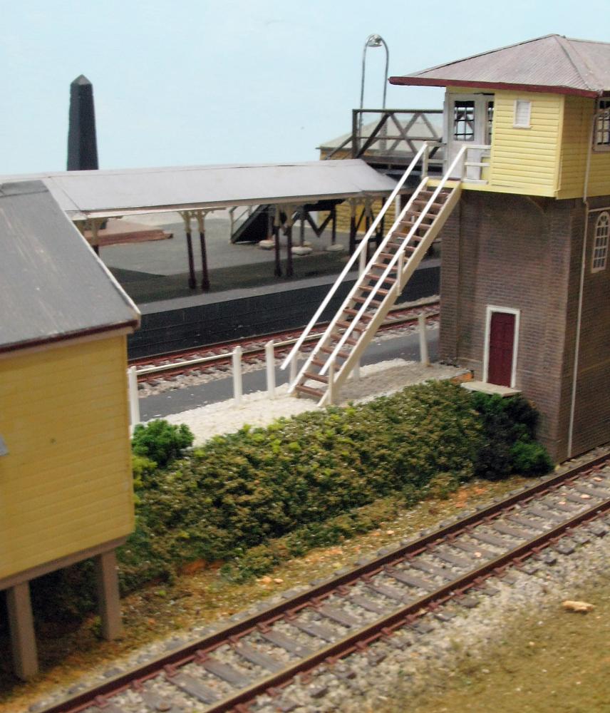
The newly installed signal box steps and platform railing.
Steps were added to Wallarawang East signal box. The stringers and treads were made from 10" x 2" styrene strip. One stringer was cut to length, with the bottom angle cut and the top notched, all by trial and error, so that it sat neatly against the first floor landing and the ground at a realistic looking angle. The first stringer was then used as a template for the second stringer. Treads were cut to length using a chopper to ensure equal length for each tread.
One stringer was pencil marked with equal spacing for where the treads would be fixed to it. The top tread and the bottom tread were installed first, holding the whole thing together so all the other treads could be installed between them. Getting the first two treads in was tricky and required two pairs of hands to hold things steady and in the right place. It also required a lot of patience. Each tread was held with tweezers and MEK was dabbed on with a very small brush, and then glued into position.
The step assembly was then glued into place between the ground and the first floor landing. The handrail was made from 2" x 2" styrene strip for the verticals, and 3" x 2" strip for the handrails. The verticals were glued to the outside of each stringer, and then the tops were angle cut to match the angle of the stringer. The handrail was then glued on top of the verticals. Once all the glue had fully dried we gave the whole thing a coat of white paint, and then painted the surface of the step treads brown.
After studying old photos we realised parts of the Down platform had a simple fence. It appeared to be constructed of old rail for the posts, and a single top railing of galvanised water pipe, all painted white. Evergreen styrene H-section was used to represent the old rail, cut into short lengths with the top of each post cut at 45 degrees, which were then inserted into holes drilled into the back of the platform. Small holes were drilled into the web at the top of each of the posts. A length of brass wire was threaded through these small holes and glued in. The whole assembly was then carefully painted white with a fine brush.


